


The Silent HDMI® Gatekeeper
What Every Engineer and Integrator Should Know
The Hidden Control Plane
Within the HDMI ecosystem, attention is naturally drawn to the high-speed data lanes that carry Audio and Video content at rates reaching tens of gigabits per second. Yet before any of that payload is transmitted, a far slower and often overlooked subsystem determines whether the link will function at all. This subsystem is the Display Data Channel, commonly referred to as DDC. Built upon a modest serial based I²C interface operating at approximately 100 kHz, serves as the foundational control plane that enables discovery, negotiation, authentication and ongoing link management between source and sink devices.
The contrast is striking. A multi-gigabit link, highly engineered and tightly controlled tolerances, is entirely dependent on a two-wire serial bus designed for limited distances, inherently analog in behavior and vulnerable to capacitance, noise and timing distortion. Despite this apparent simplicity, the DDC bus carries a surprisingly rich set of structured data types, each with its own protocol layer and timing sensitivity.
Since HDMI®’s inception, widespread interoperability issues have often been attributed to the high-speed video portion of the interface. While those data lanes are unquestionably critical to overall system performance, studies conducted at DPL Labs® have demonstrated that the majority of real-world failures originate within the DDC channel rather than the high-speed paths. Understanding these data types and how they traverse the bus is therefore fundamental to understanding HDMI® interoperability itself.
DDC: A System Within a System
The HDMI Display Data Channel (DDC) is far more than a simple conduit for EDID information. It is a layered communication system that carries multiple classes of data, each critical to the operation of the interface. From static capability descriptors to dynamic link management and secure authentication, all of these functions are multiplexed over a fragile two wire bus.
This complexity is often hidden from view, overshadowed by the high-speed data channels that dominate performance discussions. Yet in practice, the reliability of the entire system depends on the integrity of this low speed link. It is here that theoretical compliance meets real world behavior, and where small imperfections can have disproportionate impact.
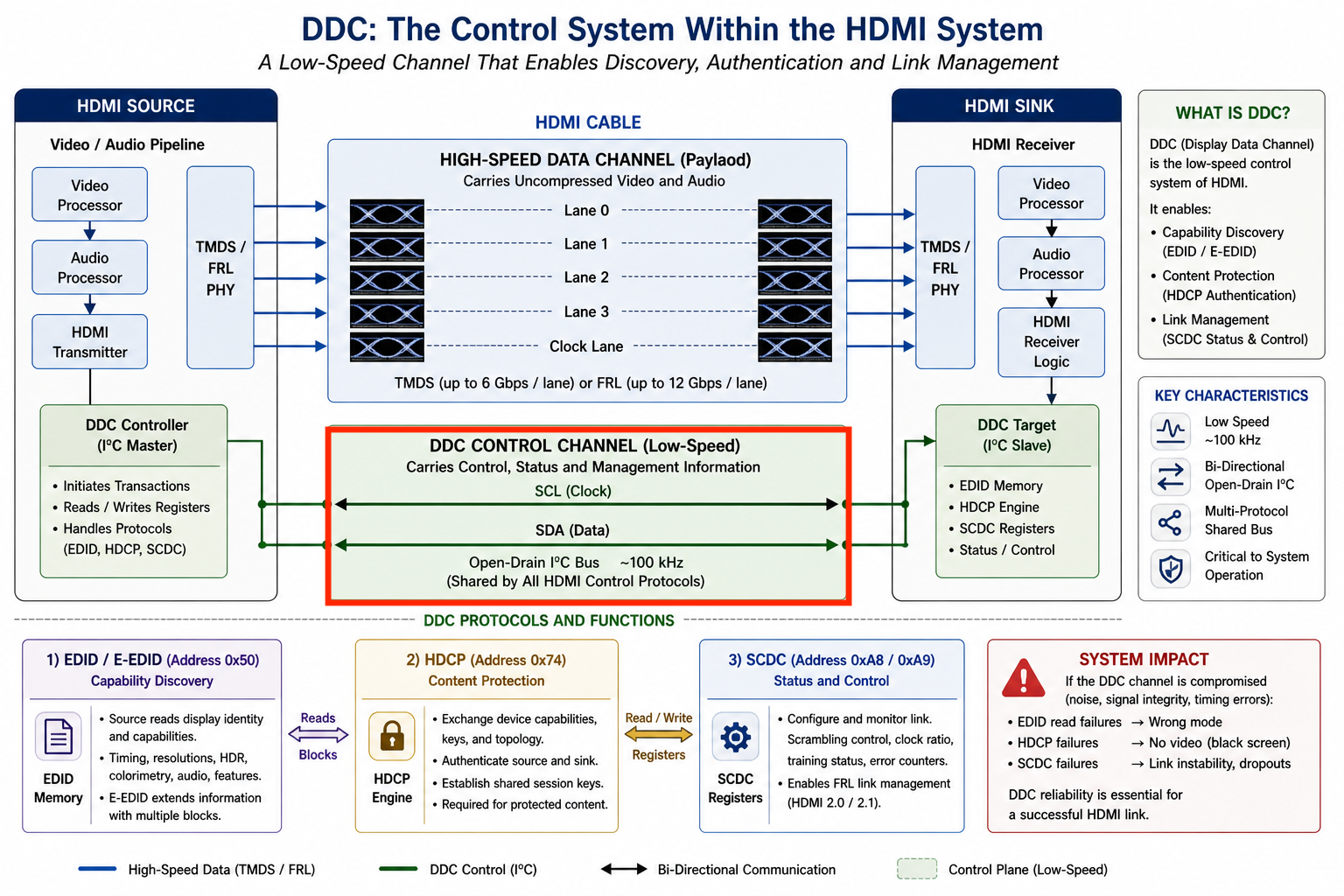
In a laboratory context, this reinforces a fundamental truth. High speed performance cannot be evaluated in isolation. The control plane must be equally robust, as it defines the conditions under which the data plane operates. The DDC bus, though simple in appearance, embodies this principle. It is both the foundation and the potential point of failure for the entire HDMI ecosystem.
Physical and Protocol Foundation
At the electrical level, DDC is implemented as an open drain, bidirectional I²C bus consisting of a clock line and a data line. Both lines are pulled up by way of pull up resistors to a 5-volt rail provided by the HDMI source, and communication occurs through controlled sinking of current by either device. Each clock pulse effectively catches the data pulse coming down the data line one bit at a time. Here, in this example, it reads 1100100. The sink typically hosts memory mapped registers, while the source initiates transactions, although certain protocols introduce quasi bidirectional behavior.
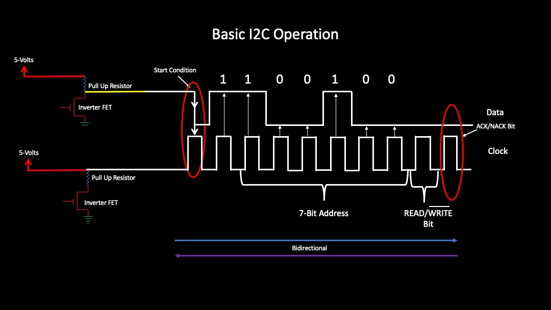
Because the bus is shared across multiple logical protocols, it operates as a multiplexed transport layer. Addressing is performed using standard 7 bit I²C conventions, with specific address ranges reserved for EDID access, HDCP transactions and SCDC control. This shared nature introduces an important constraint. All data types must coexist on the same physical medium, competing for timing, bandwidth and signal integrity. The result is a system where low speed signaling integrity can become even more critical than the interfaces high speed channel performance.
EDID and E-EDID: Capability Discovery
Upon HDMI’s initial release the most fundamental data transported over DDC was the Extended Display Identification Data, or EDID. This dataset represents the identity and capabilities of the display device and is the first information requested by the source during connection. Without it, the HDMI interface loses its ability to automatically configure itself, reducing interoperability to guesswork.
EDID is structured as a series of 128-byte blocks, beginning with a base block that contains manufacturer identification, product codes, serial numbers and basic display characteristics. Additional extension blocks expand this information to include detailed timing descriptors, colorimetry support, audio capabilities and advanced features such as high dynamic range metadata. These extensions are collectively referred to as Enhanced EDID, or E EDID, and can scale to multiple blocks depending on the complexity of the display.
As this data is read across the DDC bus, it effectively establishes a contract between the source and sink. The source interprets supported resolutions, refresh rates and color formats and configures its output accordingly. Audio capabilities define channel counts and codec support, while vendor specific extensions may signal support for proprietary features such as advanced HDR formats or high bandwidth link modes.
From a transport perspective, EDID reads are sequential and often involve segmented addressing when multiple blocks are present. The process is highly sensitive to timing distortions such as poor waveforms or clock stretching anomalies. When failures occur, they manifest as incorrect mode selection, loss of advanced features or complete inability to establish a video link.
HDCP: Authentication and Encryption Exchange
Beyond capability discovery, the DDC bus carries the full HDCP authentication process. High-bandwidth Digital Content Protection depends on this low-speed channel to exchange the cryptographic information required to secure the video stream. Without successful completion of this exchange, protected content cannot be displayed.
During authentication, the bus transports device capabilities with key selection vectors and derived session keys. Each device presents a unique identifier, and through a coordinated sequence of read and write operations, the source and sink establish a shared encryption context. In systems that include repeaters, additional topology data is exchanged, defining the number of downstream devices and the depth of the connection chain.
This exchange is highly time sensitive. While the bandwidth requirement is minimal, the order and timing of transactions must remain within tight tolerances. Even subtle degradation of the DDC signal, such as waveform distortion caused by poor cable performance, can disrupt the handshake. When this occurs, the result is typically a complete loss of video, often perceived by the user as a black screen.

SCDC: Real Time Link Management
As HDMI evolved into higher bandwidth regimes, the role of DDC expanded even further to include real time link management identified as the Status and Control Data Channel. This protocol operates over the same physical lines but introduces a new class of dynamic data used to configure and monitor the high-speed link.
Through SCDC, the source can enable or disable scrambling, adjust clock ratios, monitor link status and error correction. In modern implementations, particularly those using Fixed Rate Link signaling, SCDC becomes essential for link training and stability. The sink reports lane lock status and error conditions, allowing the source to adapt its transmission parameters.
This creates a feedback loop that did not exist in earlier HDMI generations Rev 2.0. Rather than relying solely on static configuration derived from EDID, the system can now respond to real world conditions such as marginal cables or environmental noise. The data transferred in this context includes configuration registers, status flags and error counters, all of which are accessed through defined register maps.
The significance of this cannot be overstated. At high data rates, the link operates on the edge of physical limits. SCDC provides visibility into that margin, effectively exposing the difference between a link that is merely functional and one that is robust by correcting interface performance problems that was never achievable in pre SCDC environments.
DDC/CI: Interactive Display Control
In addition to discovery and authentication, the DDC bus also supports an interactive control protocol known as DDC/CI. This allows the source or host system to directly manipulate display settings such as brightness, contrast and input selection.
The data exchanged in this context follows the Monitor Control Command Set and consists of structured command and response packets. Compared to EDID and HDCP, these transactions are less time critical and typically occur during normal operation rather than initialization. Nevertheless, they share the same physical medium and are subject to the same signal integrity constraints.
DDC/CI is widely used in desktop environments and professional calibration systems, providing a standardized method for controlling display parameters without requiring separate interfaces. While not essential for basic HDMI functionality, it represents an additional layer of complexity within the DDC ecosystem.
Vendor Specific and Auxiliary Data
Beyond standardized protocols, the DDC bus is often used for proprietary and auxiliary data exchanges. Manufacturers may implement custom extensions to support unique features or to facilitate diagnostics and firmware updates. In laboratory environments, this capability is frequently leveraged by test equipment and emulators, transforming the DDC bus into an active interface for experimentation and validation.
These transactions may not be formally documented, yet they coexist with standard protocols and contribute to the overall behavior of the system. This further reinforces the concept of DDC as a shared and multifaceted communication channel rather than a single purpose interface.
Signal Integrity and Failure Mechanisms
From an engineering perspective, the reliability of all these data types is governed by the analog behavior of the DDC lines. The bus is highly sensitive to capacitance, which increases with cable length and can significantly slow signal transitions. Rise times that extend into hundreds of nanoseconds reduce noise margins and increase susceptibility to timing violations.
Crosstalk from adjacent high-speed pairs and variations in pull up resistance further complicate the signal environment. Unlike high speed differential signaling, which can tolerate some degree of noise through encoding and error correction, the I²C based DDC bus has limited resilience. Errors are not gracefully degraded but instead result in complete transaction failure.
Each class of data exhibits distinct failure symptoms. Errors in EDID transfer lead to incorrect configuration or lack of video. Failures in HDCP authentication result in immediate content protection issues, typically seen as a blank display. Problems in SCDC communication can cause instability at higher data rates, manifesting as intermittent dropouts. Even DDC/CI failures can disrupt user control, though these are generally less critical.
The key observation is that DDC failures are binary in nature. The system either functions correctly or it does not function at all. This aligns with the broader behavior of digital communication systems operating near their limits, where margins collapse abruptly rather than gradually.
Architectural Perspective
The reliance of a high bandwidth interface on a low speed control bus presents a fundamental architectural paradox. The entire HDMI system depends on the integrity of a communication channel that is orders of magnitude slower and far more susceptible to analog degradation.
This creates a single point of failure that is often underestimated. While significant effort is invested in ensuring the quality of high-speed channels, the DDC bus is frequently treated as an afterthought. In practice, it is the gatekeeper of the entire link, determining whether communication can even begin.
From a system design standpoint, this highlights the importance of treating DDC with the same level of rigor as the primary data path. Proper impedance control, careful management of capacitance and thorough validation under real world conditions are essential to achieving reliable performance.