
Transmission Lines
“Differentially Speaking“
The history of balanced and unbalanced transmission lines is, at its core, the history of how engineers learned to preserve information as it moves through imperfect environments. Whether that information is a human voice, a musical performance or a multi-gigabit digital stream, the challenge has always been the same: how do you move a signal from one place to another with minimal loss of integrity?
Unlike conventional DC or AC power delivery, where the primary concern is transferring energy from source to load, signal transmission systems are fundamentally concerned with preserving the accuracy and timing of information. In many cases, the actual power involved in a signal transmission path is extremely small. What matters most is not how much energy arrives at the destination, but whether the waveform arrives without distortion, noise or timing errors. As frequencies increase and signaling speeds rise, preserving the integrity of the information itself becomes significantly more critical than the transfer of electrical power alone.
When a Wire Becomes a Transmission Line
A transmission line is a structure designed to carry electrical energy or signals from one point to another while preserving their integrity. Although the concept may appear simple, a true transmission line is defined not just by its ability to conduct electricity, but by how it behaves when signals travel through it, especially at higher frequencies or over longer distances.
At low frequencies and short distances, a wire can often be treated as a simple connection. As signal frequency increases or as cable length becomes significant relative to the signal wavelength, the behavior of the conductor changes fundamentally. The wire no longer functions as a simple electrical path but instead assumes the characteristics of a true transmission line.
As a transmission line the cable now exhibits distributed electrical effects including resistance, capacitance and inductance present continuously along the entire cable length. 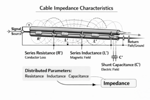 These form a distributed circuit in which resistance and inductance appear in series along the conductor, while capacitance exists between the conductor and its return path or ground. Together, they create a relatively complex series/parallel network extending across the entire cable. These effects introduce certain anomalies, ultimately degrading overall system performance.
A key property of any transmission line is its characteristic impedance, which is determined by its physical geometry and materials. This impedance defines how signals propagate along the transmission line. Common examples include 50-ohm and 75-ohm coaxial cables used in RF and video applications, as well as 100 ohm twisted pair cables used in data communications.
When a signal travels down a transmission line, it does so as an electromagnetic wave. The energy is not confined solely to the conductor itself but exists in the electromagnetic field surrounding it. This is why the spacing between conductors, the dielectric material and the overall construction play such a critical role in performance.
Impedance Matching
One of the most critical considerations in transmission line theory is impedance matching. When the impedance of any source, transmission line and load are not equal, a portion of the signal is reflected back to where it came from, leading to performance degradation and signal integrity issues.
Proper termination of a transmission line ensures that the signal is totally absorbed by the load and not reflected back, literally throwing it away.
Transmission lines come in several common forms. Coaxial cable is widely used for radio frequency and video signals due to its shielding and controlled impedance. Twisted pair cable is commonly used in networking and telecommunications, where its twisted pair structure helps reduce noise. Printed circuit board traces also act as transmission lines at high frequencies, requiring carefully designed artwork to maintain signal integrity.
The earliest transmission systems were inherently unbalanced. In the mid 19th century, during the rapid expansion of the telegraph, a single conductor carried the signal while the Earth itself served as the return path. This approach was simple, economical and effective over long distances, but it came with a cost. Because the signal was referenced to ground, it was vulnerable to environmental noise, lightning interference and variations in ground potential. At the time, the industry accepted these limitations because the signals were relatively slow, and the technology had not yet matured.
Differential Signaling
As telephone emerged toward the end of the 19th century, the limitations of unbalanced transmissions became more apparent. Carrying intelligible voice over long distances required greater fidelity and lower noise. This led to the development of the balanced transmission line. This principle would later be formalized as Differential Signaling.
Instead of relying on ground as a reference, engineers began using two conductors, each carrying equal and opposite versions of the signal. This configuration dramatically reduced susceptibility to external noise because interference tended to couple equally into both conductors. 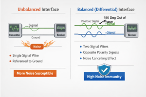 At the receiving end, only the difference between the two signals was amplified, effectively canceling the unwanted noise component. This behavior is known as Common-mode Rejection. The degree to which a system can reject common mode noise depends on how well the system maintains its signal symmetry. Imperfections in cable construction, connector and printed circuit board design can degrade this performance.
At the same time, unbalanced transmission did not disappear. It continued to thrive in applications where simplicity, cost and short cable lengths made its limitations acceptable. Early radio systems, consumer audio equipment and instrumentation still used unbalanced connections. The familiar coaxial cable is a refined example of an unbalanced transmission line. It uses a central conductor surrounded by a shield that serves as both return path and protection against external interference. While coaxial designs improve shielding compared to a simple single wire, the signal is still referenced to ground, which means it does not benefit from the inherent noise rejection of a balanced line system.
The audio industry provides one of the clearest illustrations of the divergence between balanced and unbalanced approaches. In professional audio environments such as recording studios and live sound reinforcement, balanced lines became the standard. Microphones, which produce very low-level signals, are particularly susceptible to noise. By using balanced line cables and connectors, engineers were able to run long cables across stages and through venues substantially reducing hum or interference. The balanced line microphone became synonymous with reliability and fidelity.
This division between professional balanced systems and consumer unbalanced systems persisted for decades and still exists to a certain point today, although the boundaries have blurred as technology has advanced.
Digital Applications
As electronic systems evolved in the 20th century, the principles of balanced transmission began to influence other domains. In instrumentation and industrial control systems, balanced lines were used to improve measurement accuracy in electrically noisy environments. Laboratories and manufacturing facilities often contained motors, switching equipment and other sources of interference. Balanced transmission allowed sensitive signals to coexist with these disturbances.
The transition from analog to digital signaling in the latter half of the 20th century introduced new challenges. Digital signals, particularly at high speeds, are sensitive not only to noise but also to timing distortions, reflections and impedance mismatches. Early digital systems often used unbalanced signaling, especially for short distances on circuit boards. However, as data rates increased, the limitations of single ended (unbalanced) signaling became more pronounced.
This led to the widespread adoption of differential techniques in digital electronics. Differential signaling is, in many ways, a direct descendant of the balanced line concept developed for telephone. By transmitting complementary signals on a pair of conductors and detecting their out of phase difference at the receiver, engineers achieved improved noise immunity and reduced electromagnetic emissions. These characteristics became essential as clock frequencies and data rates climbed into the hundreds of megahertz and beyond.
 One of the key advantages of differential signaling in digital systems is its ability to reduce radiated emissions. Because the currents in the two conductors are equal and opposite, the electromagnetic fields they produce tend to cancel each other. This makes differential pairs inherently quieter in terms of electromagnetic interference. At the same time, they are less susceptible to external noise, creating a two-way benefit that is difficult to achieve without differential signaling.
The rise of high-speed digital interfaces further cemented the importance of differential transmission. Standards such as USB, Ethernet, HDMI and DisplayPort all rely on differential pairs to achieve their performance targets. These systems operate at data rates that would be impractical with traditional unbalanced approaches.
In the case of Ethernet, the use of balanced twisted pair cabling can be traced directly back to telephone technology.  Modern Ethernet cables contain multiple twisted pairs, each carefully engineered to maintain impedance control and minimize crosstalk. The lineage from early telephone to modern networking is both direct and profound.
In video transmission, interfaces such as HDMI and DisplayPort use multiple differential lanes to carry enormous amounts of data. For example, high bandwidth video formats require several parallel differential channels operating simultaneously. The integrity of each channel depends on precise control of impedance, timing and polarity. Even small deviations can lead to errors, highlighting the importance of proper design and manufacturing.
The relationship between balanced lines in analog systems and differential signaling in digital systems is not merely conceptual. It is a direct evolution of the same idea applied to different domains. In both cases, the goal is to preserve the integrity of a signal by rejecting unwanted noise and interference. The difference lies in the nature of the signals themselves. Analog systems focus on preserving continuous waveforms with high fidelity, while digital systems focus on maintaining discrete logic states and precise timing relationships.
Another important aspect of this evolution is the increasing importance of system level design. In early telegraph and telephone systems, the focus was on the transmission line itself. As technology advanced, attention shifted to the interaction between the transmission line, the transmitter and the receiver. In modern high-speed digital systems, the entire signal path is treated as an integrated system. This includes the printed circuit board traces, connectors, cables and termination networks. Each element must be carefully designed to maintain the benefits of differential signaling including impedance matching as its own component of this process. The concept of characteristic impedance, which originated in early transmission line theory, still remains central to modern design practices.
Simple Beginnings, Powerful Outcomes
The continued relevance of balanced and unbalanced transmission lines speaks to their fundamental nature. They are not merely historical artifacts but essential tools that have adapted to changing technological demands. From the telegraph wires of the 1800s to the multi gigabit links of today, the same core principles continue to apply.
In many ways, the story of these transmission methods is a story of refinement. Early engineers discovered that referencing a signal to ground was simple but imperfect. They then discovered that symmetry could be used to cancel noise and improve performance. Over time, this insight was refined, formalized and extended into new domains. What began as a practical solution to a problem in telephone has become a foundational principle in modern electronics.
Today, as data rates continue to increase and systems become more complex, the importance of these principles only grows. Differential signaling is now a cornerstone of high-speed design, and its roots in balanced transmission are a reminder that innovation often builds on ideas that are both simple and elegant.
Understanding this history provides more than just context. It offers insight into why certain design choices are made and how seemingly small details can have significant consequences. Whether in audio engineering or digital system design, the choice between balanced/differential and unbalanced/non-differential transmission systems becomes the ultimate choice about how to manage the relationship between signal and environment.
Every conductor carries more than just a signal
It carries the responsibility of preserving it!